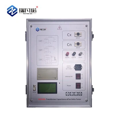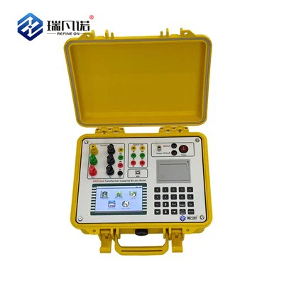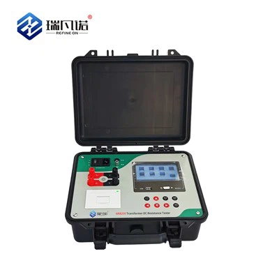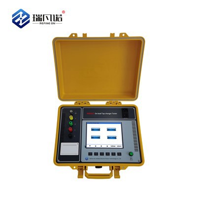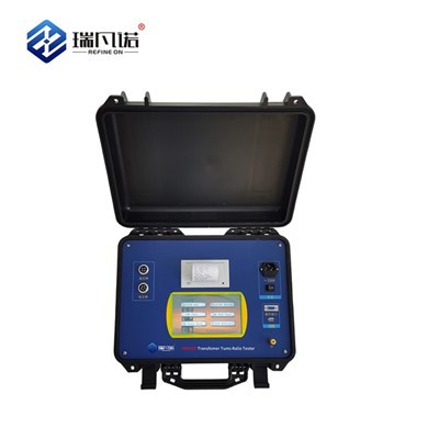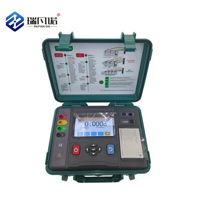

Refine On (Hebei) Electric Power Technology Co., Ltd. is one of the leading manufacturers and suppliers of vlf hipot tester in China. If you're going to wholesale durable vlf hipot tester, welcome to get quotation from our factory. All customized products are with high quality and competitive price.
High-voltage withstand testing is critical for the preventive insulation maintenance of electrical equipment. Our new-generation VLF Hipot Tester is a core product independently developed using advanced technology. It utilizes 0.1Hz ultra-low frequency testing, a method highly recommended by the International Electrotechnical Commission (IEC).
Equipped with a 7-inch touchscreen, an advanced ARM7 microcontroller, high-speed AD data acquisition circuitry, and dedicated background management software, this system successfully overcomes many common shortcomings found in similar conventional products (see Table 1). It offers an exceptional cost-performance ratio compared to imported alternatives.
The tester is engineered specifically for high-voltage withstand testing on electrical equipment with large insulation equivalent capacitance, including:Power Cables,Power Capacitors,Large and Medium-Sized Generators and Motors.This reliable, high-efficiency solution delivers international-grade precision for global industrial applications.
Performance Comparison
|
0.1Hz voltage- withstand equipment type |
HV control method |
High voltage waveform |
Energy saving |
Noise |
Lifespan |
Electrical life |
|
mechanical |
HV mechanical switch switching polarity |
Square wave |
Not energy-saving: consume excess energy with high- power resistors |
High |
short |
Short |
|
Electronic |
HV electronic switch switching polarity |
Sine wave |
Energy saving: feed back excess power to the grid |
A little |
No lifespan, can use long- term |
Long |
Table 1 performance comparison between mechanical type and electronic type of 0.1Hz voltage withstand test equipment
Advantages
Advantages of 0.1Hz ultra-low frequency withstand voltage technology
Perfect Alternative to Power Frequency Testing
This technology fully replicates the equivalence of traditional power frequency withstand tests at 0.1Hz, drastically reducing the required power supply capacity compared to conventional methods.
Highly Portable & Cost-Effective
By replacing heavy, bulky, and expensive power frequency transformers, the VLF Hipot Tester significantly reduces equipment volume and weight, making it highly portable and convenient for field use.
Safe, Non-Destructive Testing
Unlike DC high-voltage testing-which can be destructive to insulation-the AC-based 0.1Hz method ensures reliable testing without degrading the asset's insulation material (see Table 2).
Advanced ARM7 & Power Electronics
Built with the latest power electronic components and ARM7 microcontroller technology, this new-generation system delivers highly stable performance and eliminates the short lifespan and high failure rates of first-generation mechanical boosters.
User-Friendly Operation
It features an intuitive, simple interface that ensures hassle-free, "plug-and-play" operation and minimal setup time for operators.
Proven High-Voltage Capability
Extensively field-tested with proven capabilities up to 80kV, this VLF Hipot Tester has received outstanding user feedback, confirming it offers an exceptional performance-to-cost ratio for global industrial applications.
Table 2
Table 2 performance comparison of various withstand voltage test equipment:
|
Compare content |
Power frequency withstand voltage |
Frequency withstand voltage |
0.1Hz withstand voltage |
DC withstand voltage |
|
Equivalence |
good |
Good |
Good |
Bad |
|
Insulation destructive |
small |
small |
small |
big |
|
Operation safety |
low |
low |
high |
A little low |
|
Wiring |
Complicated |
Most Complicated |
Most easy |
complicated |
|
Volume and weight |
Heavy and big |
Heavy and big |
Light and small size |
Light and small size |
Technical Parameters Of Series Products
Ground voltage generator
|
Model |
Rated Voltage |
Load |
Fuse |
Weight |
|
30KV /1.1 |
0.1Hz,≤1.1µF |
8A |
||
|
30kV |
0.05Hz,≤2.2µF |
Controller:6Kg |
||
|
(Peak Value) |
||||
|
0.02Hz,≤5.5µF |
Booster:20Kg |
|||
|
60kV/1.1 |
0.1Hz,≤1.1µF |
10A |
||
|
60kV |
0.05Hz,≤2.2µF |
Controller:6Kg |
||
|
(Peak Value) |
||||
|
0.02Hz,≤5.5µF |
Booster:45Kg |
|||
|
80KV/0.5 |
0.1Hz,≤1.1µF |
20A |
||
|
80kV |
0.05Hz,≤2.2µF |
Controller:6Kg |
||
|
(Peak Value) |
||||
|
0.02Hz,≤5.5µF |
booster:50Kg |
|||
|
90KV/0.5 |
0.1Hz,≤1.1µF |
20A |
||
|
90kV |
0.05Hz,≤2.2µF |
Controller:6Kg |
||
|
(Peak Value) |
||||
|
0.02Hz,≤5.5µF |
booster:55Kg |
Select products of appropriate specifications according to the subjects
When in use, the capacitance of the test object shall not exceed the rated capacitance of the instrument. If the capacitance of the test object is too small, the output waveform will be affected. If it is less than 0.05 μ F, the instrument will not output normally. At this time, 0.05 μ f capacitor (provided by the company) can be connected in parallel for auxiliary output. See Table 4 and table 5 for the estimation of capacitance of common electrical equipment.
Table 4 single phase earth capacity of different types of generators.
|
Steam turbine generator |
Hydro generator |
||||||
|
Capacity (MW) |
200 |
300 |
600 |
85 |
125- 150 |
300 |
400 |
|
Single phase ground capacitance(uF) |
0.198 |
0.18- 0.26 |
0.31- 0.34 |
0.69 |
1.8-1.9 |
1.7-2.5 |
2.0-2.5 |
Table 5 capacitance of XLPE insulated single core power cable (μ f / km)
|
Voltage(KV) capacitance (uf/Km) Cross-sectional area (mm) |
16 |
25 |
35 |
50 |
70 |
95 |
120 |
150 |
185 |
240 |
|
10 |
0.15 |
0. 17 |
0.1 8 |
0.19 |
0.2 1 |
0.2 4 |
0.26 |
0.2 8 |
0.32 |
0.38 |
|
35 |
- |
- |
- |
0.11 |
0.1 2 |
0.1 3 |
0.14 |
0.1 5 |
0.16 |
0.17 |
Estimation method of test object current:
Calculation formula: I = 2 π FCU
VLF Hipot Tester features
Advanced technology: digital frequency conversion technology, microcomputer control, pressure rise, pressure reduction, measurement, protection, etc
The test process is fully automated.
Easy to operate: simple wiring, fool operation.
Comprehensive protection: multiple protection (over-voltage protection, over- current protection at high and low voltage sides), rapid action (when acting)
Room ≤10ms), the instrument is safe and reliable.
Safety and reliability: the controller is connected with the low voltage of the high voltage generator, with photoelectric control, safe and reliable use.
The high and low voltage closed-loop negative feedback control circuit is adopted, and the output has no capacity rise effect.
Complete configuration: capacitive touch screen, LCD Chinese character display, automatic storage, automatic printing.
Large test range: 0.1Hz, 0.05Hz and 0.02hz multi frequency selection, large test range.
Small volume and light weight: it is very convenient for outdoor operation.
Instrument structure and function description
The VLF Hipot Tester consists of two parts: controller and booster. The structure and function of the two parts are as follows:
1.The layout of each part of the controller panel is shown in Figure 1, and the function description of each part is as follows:
Figure 1 Schematic diagram of controller panel

"Terminal" -Grounding terminal: it is connected with the earth when in use.
"Switch" - power switch: built-in indicator light, on when on, off when "AC220V" - power input socket, built-in fuse.
"Printer" - print test reports.
"Capacitive touch screen" - display test data and output waveform, and can be operated
directly on the screen by hand.
"USB" - its function is used to communicate with the upper computer. "Stop" - for emergency stop test.
2.Structure diagram of booster

Figure 2 Schematic diagram of booster structure
Operation instructions
1.Ultra low frequency output wiring method

Figure 3 wiring diagram
Wiring instructions: connect the control output special line, high voltage output special line and grounding wire equipped with the product according to the method shown in Figure 3. The power cord of the power socket is connected to the AC of 220V / 50Hz.
2.Operation procedure
startup, shutdown and reset
After connecting all the lines according to the above method, the power switch can be turned on. After the microcomputer is powered on or reset, the instrument will automatically enter the interface as shown in Figure 4. When connecting wires, removing wires, or temporarily not using the instrument, turn off the power supply. The power socket is equipped with a safety tube. If there is no display on the start- up screen, check whether the fuse is broken first, and the size of the fuse shall be replaced according to the data provided in Table 3.

Figure 4 Schematic diagram of touch screen
Set parameters

Figure 5 parameter setting interface
First, click the "setting" button on the screen of Figure 4 to display the setting parameter interface shown in Figure 5. In Figure 5, the output frequency, test time, test voltage, overcurrent protection value and overvoltage protection value on the high voltage side can be set according to the needs of the test. The modification method is as follows:
★ There are three options for frequency: 0.1, 0.05 and 0.02, and the unit is Hz.
★ Timing modification range: 0-99 points. It specifies the duration of the test, in minutes.
★ Set voltage: range from 0 to rated value, unit: kv. It sets the test voltage we want to raise. When the instrument rises to this set voltage limit, it will no longer boost voltage, and maintain constant amplitude sine wave output at this peak value.
★ Set voltage limit: the setting range of voltage protection value is from 0 to rated value, and the unit is kv. It specifies the upper limit value of the voltage passing the test object. When the voltage exceeds this setting, the instrument will automatically cut off the output.
★ Setting current limit: the setting range of current protection value is from 0 to rated value, and the unit is ma. It specifies the upper limit value of current passing through the test object. When the current exceeds this setting, the instrument will automatically cut off the output.
(Note: the above voltage, current and measurement data displayed by the instrument are all peak values.)
automatic boosting
After pressing the "start" key in Figure 4, the instrument will carry out the boosting test under the control of the computer as follows:
Self-inspection →boosting →constant amplitude output →shutdown The
specific process is as follows:
Self inspection process
The controller automatically enters the load detection. If no load is detected, the prompt message "load not connected" in the status bar of Figure 6 indicates that the booster or capacitive test sample is not connected.

Figure 6 the controller indicates that the load is not connected
Boosting process
After the self-test is successful, the instrument will automatically enter the boosting state, as shown in Figure 7, and the prompt message in the status bar is "boosting". At the same time, the timing began.

Figure 7 the controller indicates that the voltage is boosting
Equal amplitude output
The controller will raise the voltage to the set value in several cycles, and the instrument will output the equal amplitude, as shown in Figure 8. The prompt message in the status bar is "equal amplitude output".

Figure 8 constant amplitude output of controller prompt
Downtime
When the timing reaches the set time, the instrument will stop automatically, as shown in Figure 9, and the prompt message in the status bar is "stop the test".

Figure 9 controller prompts to stop the test
The instrument stops the high-voltage output and automatically discharges the test object, as shown in Figure 10. The prompt message in the status bar is "discharging".

Figure 10 the controller indicates that it is discharging
After the shutdown, as shown in Figure 11, the prompt message in the status bar is "test passed" and the data history is saved.
Note: during the test, if there is no abnormal voltage, no discharge or overcurrent protection, the test can be considered as passed.

Figure 11 controller prompt test passed
This instrument provides two shutdown modes:
★ timed shutdown: when the timing reaches the set time, the instrument will stop automatically.
★manual shutdown: click the "shutdown" key to stop the machine. The two shutdown modes are normal shutdown.
★ there are also two kinds of abnormal shutdown: over-voltage protection shutdown and over- current protection shutdown.
★ overvoltage protection shutdown
In the process of test, when the output high pressure exceeds the set limit, the instrument will automatically cut off the output after starting and shutting down the command, and then execute the data history saving. After shutting down, as shown in Figure 12, the prompt message in the status bar is "over voltage protection" and execute the data history saving.

Fig. 12 controller prompts over voltage protection
★ over current protection shutdown
In the process of test, when the output current exceeds the set limit, the instrument will automatically cut off the output after starting and stopping the command, and then
execute the data history saving. After the shutdown, as shown in Figure 13, the prompt message in the status bar: "overcurrent protection" and execute the data history saving.

Fig. 13 over current protection prompted by controller
printing
Click the "print" key in Figure 3 to print the data on the display into a test report. Under the status of viewing historical data, click the "print" key to print the historical data currently displayed on the screen.
view historical data

Figure 14 historical data interface
All the data instruments that have been shut down by timing, clicking the "stop" key, over-voltage protection and over-current protection will automatically save them as historical data. It can save
up to 64 times of measured data, and the previous 64 times will be deleted automatically. Click the "view" key in Figure 3 to open the interface in Figure 13 to view the historical data of the latest 64 tests.
Clocksetting

Figure 15 date and time setting interface
Click the "clock" button in Figure 3 to open the setting interface in Figure 15, which is used to set the date and time of the system.
Power cable withstand voltage test method
1.Disconnect all electrical equipment connected to the tested cable.
2.Use a megger to test the insulation parameters of each phase of the cable, and carry out the ultra-low frequency withstand voltage test only after the test is qualified.
3.Set the test voltage value: Umax = 3uo, where uo is the rated phase voltage of the cable. Example 1: cable parameter: the rated line voltage is 10kV, and the rated phase voltage uo = 6kV, so the test voltage setting value is:
Umax = 3uo = 18kV
See Table 4 for the setting value of 0.1Hz ultra-low frequency test voltage of various rubber and plastic insulated power cables.
Table 4 0.1Hz ultra-low frequency test voltage and time of various rubber plastic insulated power cables.
|
Rated voltage U0/US(kV) |
Handover test |
Preventive experiment |
||||
|
multi ple |
Test voltage (kV) |
Test time (mins) |
multip le |
Test voltage (kV) |
Test time (mins) |
|
|
1.8/3 |
3U0 |
5 |
60 |
3U0 |
5 |
15 |
|
3.6/6 |
3U0 |
11 |
60 |
3U0 |
11 |
15 |
|
6/6 |
3U0 |
18 |
60 |
3U0 |
18 |
15 |
|
6/10 |
3U0 |
18 |
60 |
3U0 |
18 |
15 |
|
8.7/10 |
3U0 |
26 |
60 |
3U0 |
26 |
15 |
|
12/20 |
3U0 |
36 |
60 |
3U0 |
36 |
15 |
|
21/35 |
3U0 |
63 |
60 |
3U0 |
63 |
15 |
|
26/35 |
3U0 |
78 |
60 |
3U0 |
78 |
15 |
Note: UN is the rated voltage of the cable, and uo is the phase voltage of the cable.
4.Test time: 60 minutes for handover test and 15 minutes for preventive test.
5.Setting current value of overcurrent protection:
Estimation method of capacitive current (or leakage current) of ultra-low frequency withstand
voltage test article:
Io=2πfCU=2×3.14×0.1CU(mA) (formula 1)
C is the electric capacity of the cable to the ground, unit: UF; u is the effective value of the test voltage, unit: kV.
Example 2: a 10KV (UN = 10kV, uo = 8.7kv) cable is 4km long, with a single phase to ground capacitance of 0.21uf/km and 0.1Hz super
If the low frequency test voltage is 26kv (peak value), the leakage current is approximately:
Io=2πfCU=2×3.14×0.1CU=0.628×0.21×4×26/ 2=9.69(mA)
Setting current value of overcurrent protection: I=kIo
....................................... (formula 2)
Transportation and preservation
(1)transportation
The product must be packed during transportation. Cartons can be packed in cartons or wooden boxes, and foam proof layer should be placed in the packing box. The packed products shall be able to be transported by road, railway and air. It shall not be placed in the open truck during transportation. The warehouse shall be protected from rain, dust and mechanical damage.
(2)storage
When the instrument is not used at ordinary times, it should be stored in a room with ambient humidity of - 20 ℃ ~ + 60 ℃, relative humidity of no more than 85%, ventilation and no corrosive gas. Storage should not be close to the floor and walls.
(3)moisture proof
In humid areas or wet seasons, if the instrument is not used for a long time, it is required to turn on and power on once a month (about two hours) to make the moisture emission and protect the components.
(4)anti exposure
When the instrument is used outdoors, direct sunlight exposure shall be avoided or reduced as much as possible. When the instrument is used outdoors, direct sunlight exposure shall be avoided or reduced as much as possible.
Quality assurance
The instrument is manufactured in strict accordance with national standards and enterprise standards, and each instrument is subject to strict factory inspection.
The instrument enjoys a one-year warranty period, the company will provide free warranty within warranty time and offer life-long after-sales service.
Within the service life of the instrument, the company will provide the maintenance, use training, software upgrade and other related services of the instrument for life.
If you find any problems in use, please contact our company in time, and we will solve the problems asap.
Paper change method of printer
The operation of replacing the paper roll of the printer is very simple. It does not need to take out the whole printer. Just press the open button to open the front cover. Open the front cover as shown in Figure A and take out the remaining paper core. Then install the new paper roll as shown in Figure B and close the front cover as shown in Figure C.
Note: when closing the front cover, make the printing paper stretch out from the paper outlet, put it in the middle position, and let the rubber shaft fully press the printing paper, otherwise it can't be printed. When the thermal printer is loading paper, it must be confirmed that the thermal coating of the thermal paper is on it, and then put the thermal paper into the printer paper bin. If the thermal coating is not on
the correct side, no writing will be printed. If the printing paper deviates, you can open the front cover again and adjust the position of the printing paper.

A How to open the front cover

B Printer in roll

C Close the front cover of the printe
Hot Tags: vlf hipot tester, China vlf hipot tester manufacturers, suppliers, factory, Capacitance and Dissipation Factor Tester, high voltage tan delta tester, OLTC Analyzer, Transformer Capacity and Characteristic Tester, Transformer Characteristic Tester, Transformer Parameter Tester