
How does a power quality analyzer measure frequency?
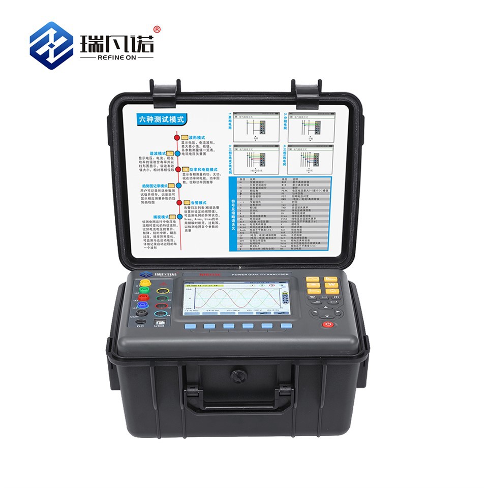
As a supplier of power quality analyzers, I often get asked about the technical details of how these devices work, especially when it comes to measuring frequency. Frequency is a fundamental parameter in electrical power systems, and accurate measurement is crucial for maintaining the stability and efficiency of electrical networks. In this blog post, I'll delve into the methods that power quality analyzers use to measure frequency and why it matters.
The Importance of Frequency in Power Systems
Before we discuss how power quality analyzers measure frequency, let's briefly understand why frequency measurement is so important. In an alternating current (AC) power system, frequency is the number of complete cycles of the alternating current that occur in one second, measured in Hertz (Hz). In most parts of the world, the standard grid frequency is either 50 Hz or 60 Hz. A stable frequency is essential for the proper operation of electrical equipment. Motors, generators, and electronic devices are designed to operate at a specific frequency, and any deviation from this can lead to equipment malfunction, reduced efficiency, and even damage over time.

Basic Principles of Frequency Measurement
Power quality analyzers use a variety of techniques to measure frequency, but most of them are based on counting the number of electrical cycles within a specific time interval. Here are some of the common methods:
Zero-Crossing Detection
One of the simplest and most widely used methods for frequency measurement is zero-crossing detection. In an AC waveform, the zero-crossing points are the instances when the voltage or current crosses the zero-voltage axis. A power quality analyzer can detect these zero-crossing points using a comparator circuit. The time interval between two consecutive zero-crossing points represents half of the period (T) of the AC waveform. Since the frequency (f) is the reciprocal of the period (f = 1/T), the analyzer can calculate the frequency by measuring this time interval and then performing the necessary arithmetic operations.
For example, if the time interval between two consecutive zero-crossing points is 10 milliseconds (0.01 seconds), the period of the waveform is 20 milliseconds (0.02 seconds). Therefore, the frequency is calculated as f = 1/0.02 = 50 Hz.
Zero-crossing detection is relatively easy to implement and provides a quick and accurate way to measure frequency. However, it can be affected by noise and harmonics in the electrical waveform, which can cause false zero-crossing detections and lead to inaccurate frequency measurements.
Phase-Locked Loop (PLL)
To overcome the limitations of zero-crossing detection, many power quality analyzers use a phase-locked loop (PLL) for frequency measurement. A PLL is a feedback control system that generates an output signal whose phase and frequency are synchronized with the input signal.
The basic components of a PLL include a phase detector, a loop filter, and a voltage-controlled oscillator (VCO). The phase detector compares the phase of the input signal (the electrical waveform) with the phase of the output signal generated by the VCO. The difference in phase generates an error signal, which is then filtered by the loop filter to remove any high-frequency noise. The filtered error signal is used to control the frequency of the VCO, adjusting it until the phase difference between the input and output signals is minimized.
Once the PLL has locked onto the input signal, the frequency of the output signal generated by the VCO is equal to the frequency of the input signal. The power quality analyzer can then measure the frequency of the VCO output signal to determine the frequency of the electrical waveform.
PLL-based frequency measurement is more accurate and robust than zero-crossing detection, especially in the presence of noise and harmonics. It can also track changes in frequency more quickly, making it suitable for applications where the frequency of the power system may vary.
Fast Fourier Transform (FFT)
Another advanced method for frequency measurement is the Fast Fourier Transform (FFT). FFT is a mathematical algorithm that decomposes a time-domain signal (such as an electrical waveform) into its frequency components. A power quality analyzer that uses FFT can analyze the frequency spectrum of the electrical waveform and identify the fundamental frequency component.
The analyzer first samples the electrical waveform at a high rate to obtain a discrete-time signal. It then applies the FFT algorithm to the sampled data to transform it from the time domain to the frequency domain. The resulting frequency spectrum shows the amplitude of each frequency component present in the waveform. The power quality analyzer can then determine the fundamental frequency by identifying the frequency component with the highest amplitude.
FFT-based frequency measurement provides a more detailed analysis of the electrical waveform and can also detect the presence of harmonics and other frequency components. However, it requires more computational power and processing time compared to zero-crossing detection and PLL methods.
Frequency Measurement in Power Quality Analyzers
In a power quality analyzer, the frequency measurement function is usually integrated with other measurement functions, such as voltage, current, and power measurement. The analyzer continuously samples the electrical signals and performs the necessary calculations to measure the frequency in real-time.
Most power quality analyzers have a high level of accuracy and can measure frequency with an error of less than ±0.01 Hz. They also have the ability to display the measured frequency on a digital screen and record the data for later analysis. Some advanced power quality analyzers can even communicate with a computer or other monitoring devices to transmit the measured frequency data remotely.
Why Choose Our Power Quality Analyzers for Frequency Measurement
As a leading supplier of power quality analyzers, we offer a range of high-quality products that are designed to provide accurate and reliable frequency measurement. Our power quality analyzers are equipped with advanced measurement technologies, such as PLL and FFT, to ensure accurate frequency measurement even in the presence of noise and harmonics.
Our analyzers also offer a user-friendly interface and intuitive software that make it easy to operate and analyze the measurement data. They are built to withstand harsh industrial environments and have a long service life, providing a cost-effective solution for power quality monitoring.
If you are interested in learning more about our Power Quality Analyzer Meter or have any questions about frequency measurement, please feel free to contact us. Our team of experts is ready to assist you in choosing the right power quality analyzer for your specific needs. Whether you are a utility company, an industrial plant, or an electrical service provider, we can help you ensure the stability and efficiency of your power system.
Get in touch with us today to start a discussion about your power quality monitoring requirements. Let's work together to keep your electrical systems running smoothly.
References
- IEEE Standard 1159-2019, Recommended Practice for Monitoring Electric Power Quality
- Grainger, J. J., & Stevenson, W. D. (1994). Power System Analysis. McGraw-Hill.
- Dorf, R. C., & Bishop, R. H. (2016). Modern Control Systems. Pearson.