A ground resistance tester is used to measure the resistance of a buried grounding electrode and the soil current dissipation resistance. A ground resistance meter (or ground resistance megohmmeter) is typically used. The shape of the ground resistance meter is similar to that of a regular insulation megohmmeter, hence the common name "ground resistance megohmmeter." The external structure of the ground resistance meter varies slightly depending on the model, but the basic usage is the same. The ground resistance meter comes with two grounding probes and three wires. The usage method and measurement steps are as follows:
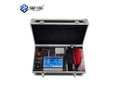
(a) Ground Resistance Tester
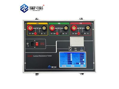
(b) Connecting Wires
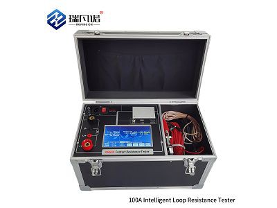
(c) Measuring Grounding Probes
1. Disconnect the connection point between the grounding main line and the grounding electrode, or disconnect all grounding branch lines on the grounding main line.
2. Insert the two grounding probes into the ground to a depth of 400mm, one 40m away from the grounding electrode and the other 20m away.
3. Place the megohmmeter on a flat surface near the grounding electrode, and then connect the wires.
(1) Connect the terminal E on the meter to the grounding electrode E′ of the grounding device using a connecting wire.
(2) Connect terminal C on the meter to the grounding rod C′ located 40m away from the grounding electrode using a connecting wire.
(3) Connect terminal P on the meter to the grounding rod P′ located 20m away from the grounding electrode using a connecting wire.

4. Adjust the coarse adjustment knob (with three adjustable ranges) according to the grounding resistance requirement of the grounding electrode being measured.
5. Rotate the meter evenly at a speed of approximately 120 revolutions per minute. When the needle deflects, immediately adjust the fine adjustment dial until the needle is centered. Multiply the reading after fine adjustment by the coarse adjustment factor to obtain the grounding resistance of the grounding electrode being measured. For example, if the fine adjustment reading is 0.6 and the coarse adjustment resistance factor is 10, then the grounding resistance being measured is 6Ω.
6. To ensure the reliability of the measured grounding resistance value, the measurement should be repeated in a different location. Take the average value of the several measurements as the grounding resistance of the grounding electrode.