A surge arrester tester typically consists of two parts: a main unit and a voltage acquisition unit. The main unit is responsible for acquiring the leakage current of the zinc oxide surge arrester, receiving voltage signals, and performing calculations. The voltage acquisition unit is responsible for acquiring the secondary voltage of the PT or the electric field strength signal of the induction plate. Voltage acquisition supports taking voltage from the PT secondary side or acquiring electric field signals through the induction plate. Current acquisition can be achieved by sampling across a counter or by using a current clamp to capture the grounding current. Communication methods support wired synchronization, wireless synchronization, and voltage-free software simulation synchronization.
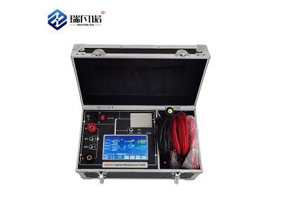
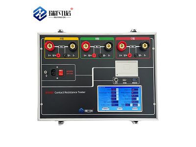
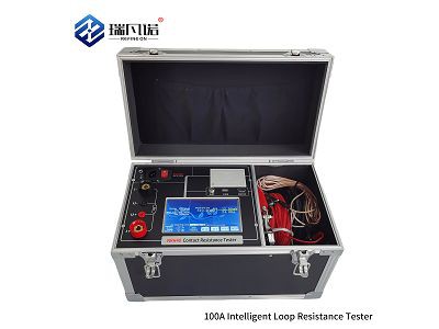
The hardware adopts a modular design architecture, including a high-precision sampling unit, signal conditioning circuit, data processing core, and display interface. The hardware uses industrial-grade components, such as high-precision AD conversion chips, anti-interference digital filters, and temperature compensation sensors. The main unit panel typically includes current input, reference signal input, LCD screen, buttons, interfaces (such as USB flash drive, printer), grounding post, and power switch. The voltage acquisition unit panel typically includes a communication interface, antenna, buttons, LCD screen, voltage input, and grounding post. The main unit's dimensions are typically between approximately 320mm×270mm×150mm and 385mm×295mm×185mm, and its weight is approximately 3.2kg to 5kg (excluding cables). Users should mainly look at the instrument's technical parameters to determine whether it meets their testing needs.